ePortefolio Ida Brandão
Arduino Programming
Resources
The Arduino Ecosystem
Circuit boards + code + community ♥ = Arduino
If someone has already told you about Arduino, it is possible that they are referring to the prototyping board of the same name: the Arduino board. In this MOOC, however, we will learn about the whole Arduino Ecosystem which is made up of:
-
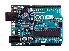
A family of boards that can be used to make electronic assemblies. There are different sizes and colors and each has different features (below left, an Arduino UNO and, right, an Arduino Nano


-
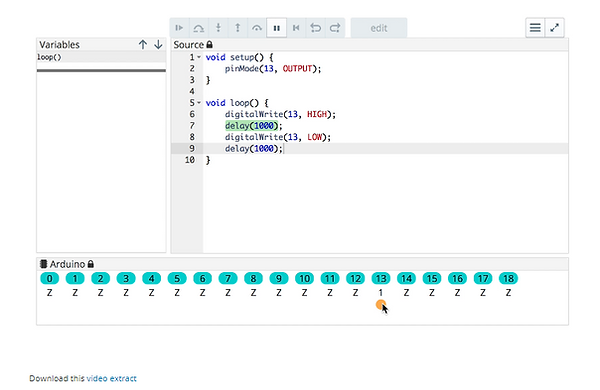
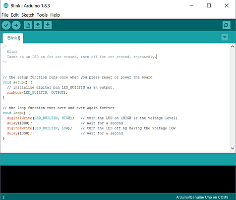
Computer software, called the Arduino IDE (Integrated Development Environment), which allows us to send instructions to the board. This software allows you to type instructions in the Arduino programming language (which is very similar to the C language). This is the famous Arduino code which we're going to discover this week. Here’s what the code looks like.Finally, there is a global Arduino community that carries out incredible projects and documents them on the Internet (like the blog of the site arduino.cc):
The history of Arduino
Created in Ivrea, Italy, in the mid-2000’s, the idea behind Arduino was to create a circuit board that was easily programmable by non-experts.
They wanted this card to be modular (suitable for use in robotics, in art, to build machines...), low-cost (< €20) and open-source (meaning that the recipe for its creation is available for free on the Internet, so that people can take the plans and make their own variants). This formula has proven so successful that today tens of thousands of artists, designers, engineers, researchers, teachers and even companies use it to carry out incredible projects, such as:
-
Capturing and analyzing scientific data from sensors for educational, research or citizen appropriation purposes;
-
Live shows – thanks to the many interaction features offered by Arduino, it is possible to create performances in VJing (DJ video), which generates real-time sound and visual effects from dancers’ movements;
-
Digital art installations – Arduino allows for the realization of works of art which can interact independently with the public;
-
Artisanal production of digital objects and low-cost machine tools in the perspective of a culture of technological appropriation that promotes DIY and organizing;
-
Rapid prototyping of innovative projects using electronics, since Arduino facilitates easy and cheap experimentation before manufacturing;
-
Fashion and textile design – several designers are exploring the possibilities offered by the integration of electronics in clothing (e-textiles);
-
Educational projects for students, professionals or the general public, from universities (such as our MOOCs), to specialized training centers or FabLabs
To see more ideas for what you can do with Arduino, check out Arduino's own project ideas website, Hackster.io's Arduino page and this page from Circuitdigest.
ARDUINO website - https://www.arduino.cc/
CIRCUIT DIGEST - Arduino Projects - https://circuitdigest.com/arduino-projects
Software for writing and checking your code
This week you’re going to learn how to type code to tell Arduino what to do. There are three tools you need for this:
1. Codecast is a very special code editor which runs entirely in your web browser. There is no need to install software on your computer for this!
2. The Arduino IDE is the preferred tool to use with the Arduino board, as it allows you to upload code to your Arduino board via USB. This software requires installation on your Windows, Linux or Mac computer.
3. Finally, the Autodesk circuits simulator will allow you to test your code and electronic fixtures, virtually! As with Codecast, this runs in your web browser, and no software installation on your computer is required.
Codecast
This week we recommend you use Codecast - http://codecast.me - to carry out the exercises, because it combines instructions typed and commented simultaneously by the instructor, and then gives you control to try to write it out yourself. The interface is fully integrated with your browser and will allow you to interact with the code and to test your knowledge within the MOOC.
Here's what it looks like:

Tinkercad circuits - https://www.tinkercad.com/circuits
Arduino and Breadboard
Here is a map that explains the connector pins found on an Arduino board:
To avoid plugging directly into the Arduino, we will use the prototyping board or breadboard.
This is worth explaining a little! Eskimon will help us:
"I will now present to you a very practical tool when one makes his debut in electronics or when one wants to test an assembly quickly/easily. This accessory is called a breadboard (technically: solderless prototyping board). To put it simply, it’s a grid of holes!"
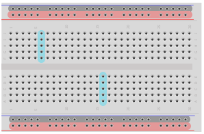
The principle of a breadboard
Of course, the board is full of holes, but many of them are connected electrically. Here is a quick diagram that will help us understand.
As you can see from the picture, I have drawn various areas. The red and black areas correspond to the power lines. Often there are two vertical lines like these that allow you to connect your components to the necessary power supplies. By convention, the Black Represents ‘ground’ at 0V, and red, the power supply (in this case, +5V). Usually, all the holes in the same horizontal ligne are connected to this area. So, you have a power line running the length of the board.
Then you can see areas in blue. These areas are linked together by connectors underneath the plastic in a vertical column – all the holes in the same column are connected to each other. However, each column is separate from the others. By overlapping components across multiple columns, you can connect them to each other.
Finally, you may notice a space that cuts the board in half symmetrically. This space also cuts the connection of the columns. Thus, in the above drawing, you can see that each column has 5 holes that are connected. The space in the middle is standardized and is the width of the standard integrated circuits (IC’s). By placing an integrated circuit in the middle, across the space in the middle, each leg lines up with its own section of a column, which you can then connect other things to.
If you want to see an example of this, I recommend you try the software Fritzing, which allows to create circuits in a fairly simple and intuitive way. You will see how the columns are separated from each other.
As we will see in the coming weeks, the pins 0 and 1 (also called Rx and Tx) can be used to communicate with the computer. We therefore recommend that you do not use these pins to connect your LEDs, but instead focus on the numbered pins from 2 to 13!
Tutorial on how to programme an Ultrasonic Sensor in Tinkercad
Tutorial on controlling a Servo Motor using Ultrasonic Sensor in Arduino
Code in - https://docs.wixstatic.com/ugd/22a975_7fc48286344544d2a2518c36943bd70f.pdf
Other projects TechExult - https://www.techexult.com/project-lessn
Tutorial on Traffic Light Sequence with Arduino - https://youtu.be/ATlEihXt2aA
Code in - https://docs.wixstatic.com/ugd/22a975_e38ce99ecdec443082ddb8922649168c.pdf
Another tutorial in Instructables about Traffic Light Sequence in Arduino - http://www.instructables.com/id/Arduino-Street-Traffic-Light/
Another tutorial about Traffic Light Sequence in Arduino - https://www.makeuseof.com/tag/arduino-traffic-light-controller/
Tinkercad Arduino tutorial Traffic Light
Button control - Edge detection
As we have seen this week, detecting the push of a button is done with the "digitalRead ()" function. However, if we put just this state reading in the main loop, we may have a few surprises.
Let's take the following code:
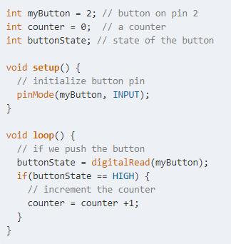
In this code, we increment a counter by 1 each time a button is pressed. At least that's what we would like ... but there's a problem! The "loop" function works very fast, so fast that your meter will increment itself many times per second, as long as your finger remains pressed on the button. But we would like it to be incremented only once per push.
This problem has a solution: edge detection!
An ‘edge’ can also be thought of as a change of state. When pressing or releasing the button, we are changing the electrical level from 0 to 1 or the opposite. This change of state represents the ‘edge’. The goal now is to pick it up in the code, in order to increment our counter once when we press the button, and not just keep incrementing many times while we hold the button down. To do that, we will have to use a variable which serves as a memory, which will allow us to compare the current state with the state on the previous run of the loop block. If the memory is different from the current state, then the button has changed state – we’ve found our edge. Otherwise, it means that the button is in the same state – no edge.
Here's how we put this into code:
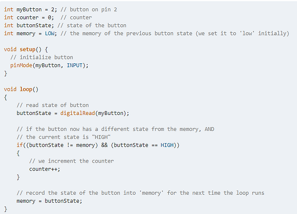
In this code, the operator "!=" means "not equal to". We compare the variable "buttonState" to the value recorded in "memory". If these two values are different, this first condition is satisfied.
The operator "&&" means "AND". This means that the block of code within the "if" brackers is only executed if both conditions either side of the "&&" are met. (buttonState!= memory) && (buttonState== HIGH).
For further information, see also the Arduino foundation's page on this topic.
Talking Electronics - http://www.talkingelectronics.com/projects/200TrCcts/200TrCcts.html